

IDENTIFYING APOGEE CONTROLLERS
Apogee Controllers
Siemens APOGEE P2 BLN Connection
The Siemens APOGEE P2 (over RS-485) network is referred to as the BLN (Building Level Network) for older APOGEE P2 hardware. Networks with newer APOGEE P2 hardware are referred to as the ALN (Automation Level Network). The BACnetP2 hardware unit needs to be connected to this BLN (ALN) for BACnetP2 operation. The BLN should, if possible, be wired using the daisy chain topology. While star topology may work (possibly at a reduced speed - BAUD rate), the daisy chain is the best.
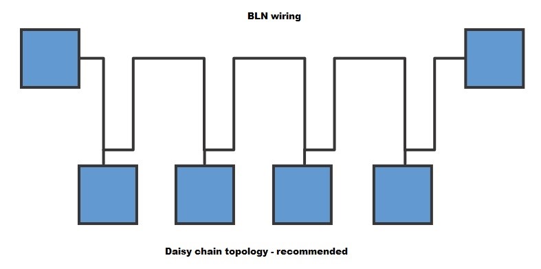
Shielded twisted pair cable should be used for the BLN connections.
There are several Siemens controllers dating back twenty five years. The section below will help in identifying the BLN connections on each of these controllers.PXC
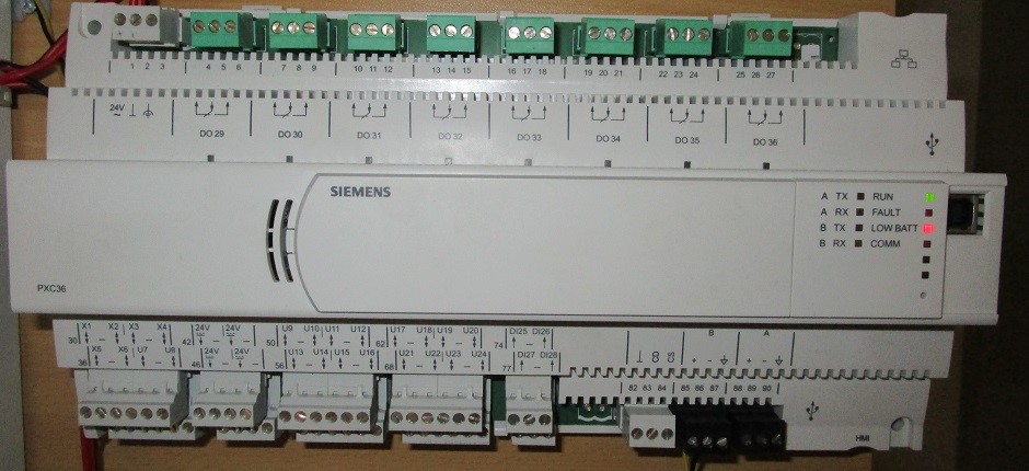
The following graphic shows the BLN connection on the PXC.
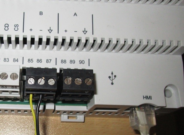
Connection "B" is the BLN. Connection "A" is the optional FLN connection.
MEC
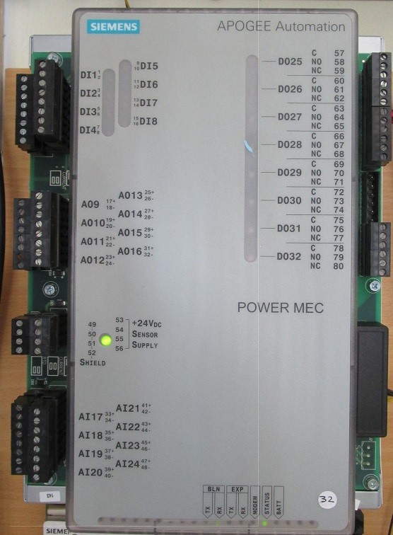
The following graphic shows the BLN connection on the MEC.
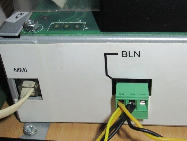
FLNC
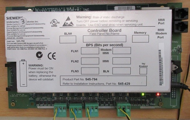
The following graphic shows the BLN connection on the FLNC.

MBC
Note that "Protocol 2" MBC controllers are NOT supported. Only "APOGEE" MBC controllers are supported. See the following graphic.
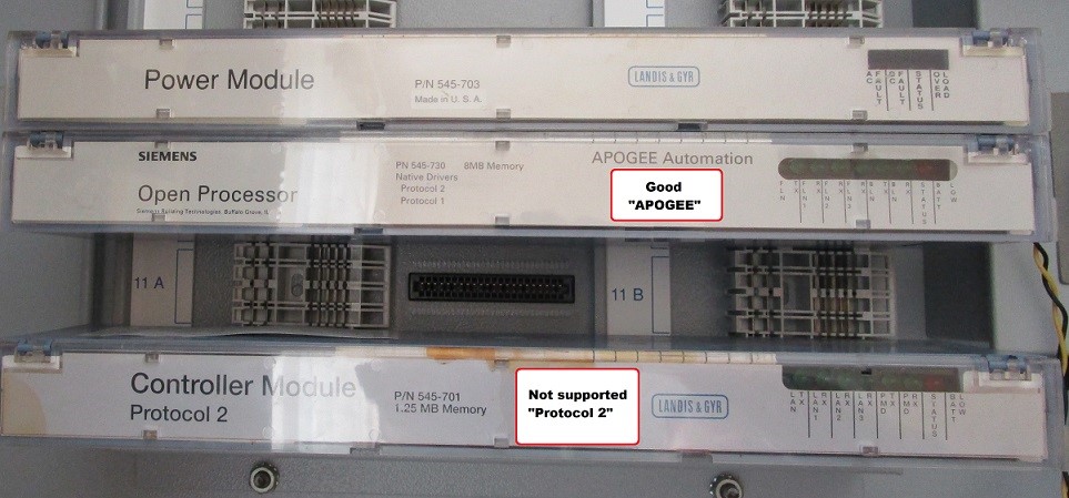
The following graphic shows the BLN connection on the MBC.
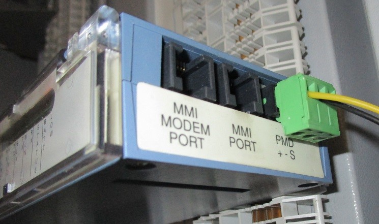
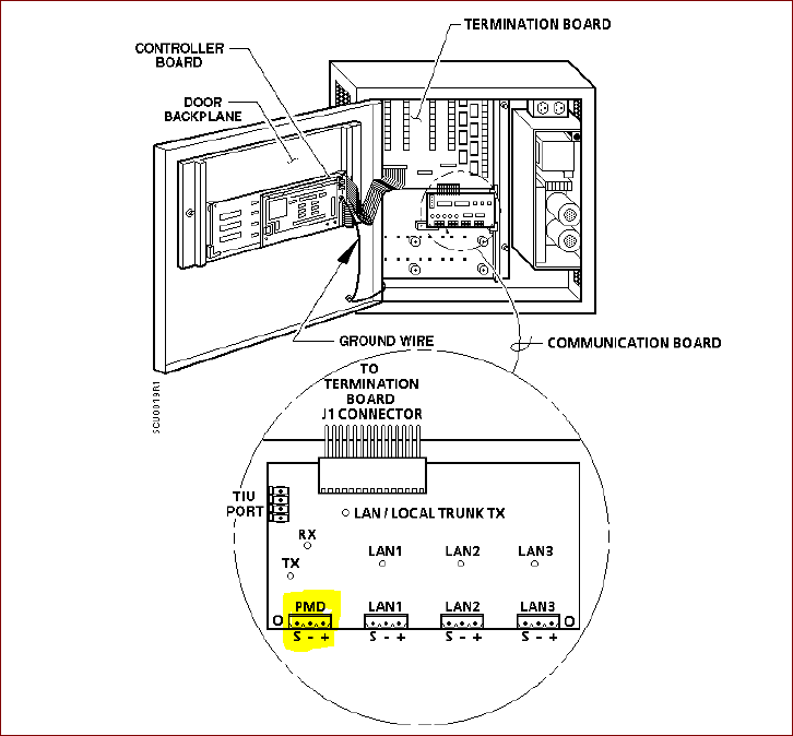
The following graphic shows the BLN connection on the SCU.
Insight® Graphics PC
The PC is usually connected via RS-232 to a "trunk interface" which has the RS-485 BLN connection.
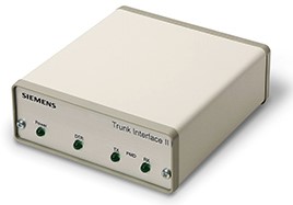
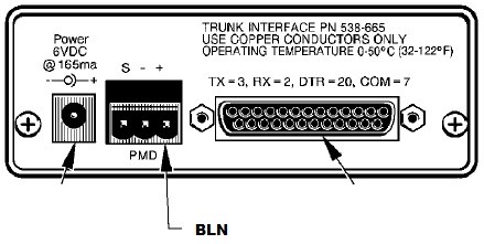
BLN connection on TI 2
End of Line (Termination) Resistors
Termination resistors may be required to ensure reliable communications. Refer to the documentation provided by Siemens.
Resources:
Modular Equipment Controller (MEC) Owner’s Manual 125-2183 Rev. 3, January, 2002. View it here: Manual